Model HPD4 Compensator
Compensators
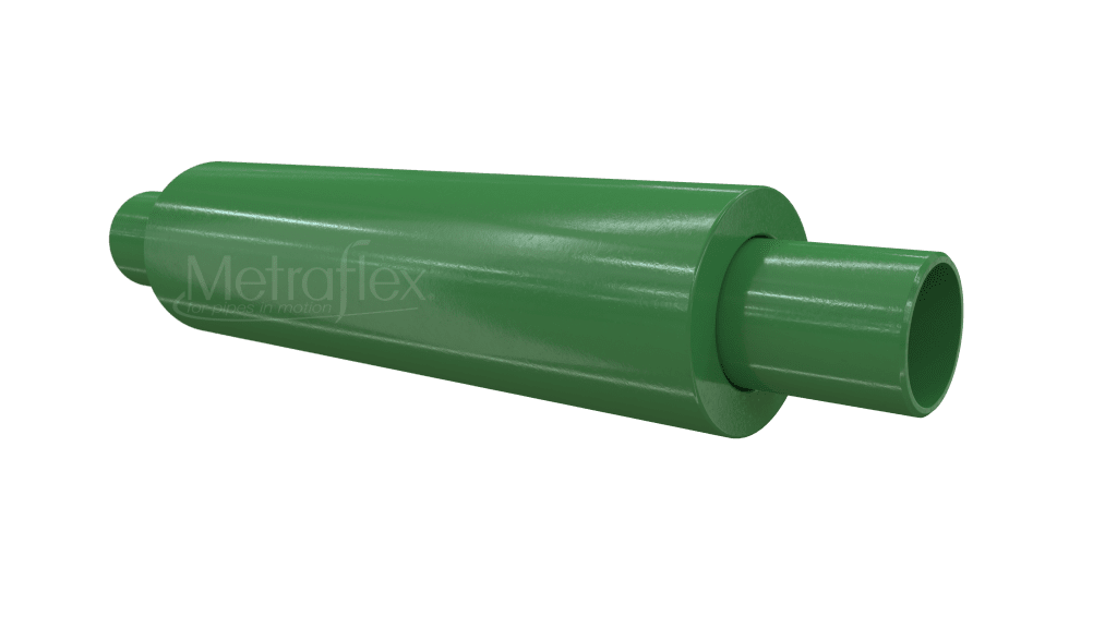
The HPD4 is a dual externally pressurized expansion compensator that has several advantages over other in-line bellows joints. Since the pressure is on the outside of the bellows, more corrugations can be added to the design resulting in a joint…
Product Description
Product Highlights
Additional Resources
Submittals
Product Description
The HPD4 is a dual externally pressurized expansion compensator that has several advantages over other in-line bellows joints. Since the pressure is on the outside of the bellows, more corrugations can be added to the design resulting in a joint capable of more movement. The design features pipe that acts as a liner and a casing that acts as a cover to protect the bellows from damage. An internal guide makes this a stable, rugged joint.
All in-line bellows expansion joints develop anchor loads and require guiding. Refer to the Expansion Joint Design Guide or consult Metraflex or your local representative for more information.
Product Highlights
- Conforms to MIL-DTL-17813H
- Maximum Working Temperature 500°F
- Maximum Working Pressure 175 PSI
- Maximum Test Pressure 250 PSI at 70°F
- Body Carbon Steel
- Bellows 2-Ply 304 Stainless Steel
- End Fittings
- 150# Carbon Steel Plate Flanges with 150 lb. drilling.
- Thread Ends (MPT with anti-torque protection)
- Weld Ends
Additional Resources
Submittals
HPD4 - Carbon Steel Body, 304 Stainless Steel Bellows, Weld Ends
| PART NO. | Pipe Size | Pressure / Temp | Compression | Extension | Effective Area (in2) |
Spring Rate (lbs/in) |
Weight | 3D Drawing |
|---|---|---|---|---|---|---|---|---|
| HPWD40075 | .75″ | 175 PSIG at 500°F. | 4″ | 1″ | 1.5 | 41 | 4 | Revit/CAD |
| HPWD40100 | 1″ | 175 PSIG at 500°F. | 4″ | 1″ | 2.1 | 44 | 6 | Revit/CAD |
| HPWD40125 | 1.25″ | 175 PSIG at 500°F. | 4″ | 1″ | 3.3 | 38 | 6 | Revit/CAD |
| HPWD40150 | 1.5″ | 175 PSIG at 500°F. | 4″ | 1″ | 4.3 | 61 | 8 | Revit/CAD |
| HPWD40200 | 2″ | 175 PSIG at 500°F. | 4″ | 1″ | 6.3 | 72 | 12 | Revit/CAD |
| HPWD40250 | 2.5″ | 175 PSIG at 500°F. | 4″ | 1″ | 8.8 | 94 | 16 | Revit/CAD |
| HPWD40300 | 3″ | 175 PSIG at 500°F. | 4″ | 1″ | 13.1 | 115 | 21 | Revit/CAD |
| HPWD40400 | 4″ | 175 PSIG at 500°F. | 4″ | 1″ | 20.8 | 242 | 28 | Revit/CAD |
HPD4 - Carbon Steel Body, 304 Stainless Steel Bellows, Thread Ends
| PART NO. | Pipe Size | Pressure / Temp | Compression | Extension | Effective Area (in2) |
Spring Rate (lbs/in) |
Weight | 3D Drawing |
|---|---|---|---|---|---|---|---|---|
| HPTD40075 | .75″ | 175 PSIG at 500°F. | 4″ | 1″ | 1.5 | 41 | 4 | Revit/CAD |
| HPTD40100 | 1″ | 175 PSIG at 500°F. | 4″ | 1″ | 2.1 | 44 | 6 | Revit/CAD |
| HPTD40125 | 1.25″ | 175 PSIG at 500°F. | 4″ | 1″ | 3.3 | 38 | 6 | Revit/CAD |
| HPTD40150 | 1.5″ | 175 PSIG at 500°F. | 4″ | 1″ | 4.3 | 61 | 8 | Revit/CAD |
| HPTD40200 | 2″ | 175 PSIG at 500°F. | 4″ | 1″ | 6.3 | 72 | 12 | Revit/CAD |
| HPTD40250 | 2.5″ | 175 PSIG at 500°F. | 4″ | 1″ | 8.8 | 94 | 16 | Revit/CAD |
| HPTD40300 | 3″ | 175 PSIG at 500°F. | 4″ | 1″ | 13.1 | 115 | 21 | Revit/CAD |
| HPTD40400 | 4″ | 175 PSIG at 500°F. | 4″ | 1″ | 20.8 | 242 | 28 | Revit/CAD |
HPD4 - Carbon Steel Body, 304 Stainless Steel Bellows, Flanged Ends
| PART NO. | Pipe Size | Pressure / Temp | Compression | Extension | Effective Area (in2) |
Spring Rate (lbs/in) |
Weight | 3D Drawing |
|---|---|---|---|---|---|---|---|---|
| HPFD40075 | .75″ | 175 PSIG at 500°F. | 4″ | 1″ | 1.5 | 41 | 10 | Revit/CAD |
| HPFD40100 | 1″ | 175 PSIG at 500°F. | 4″ | 1″ | 2.1 | 44 | 16 | Revit/CAD |
| HPFD40125 | 1.25″ | 175 PSIG at 500°F. | 4″ | 1″ | 3.3 | 38 | 23 | Revit/CAD |
| HPFD40150 | 1.5″ | 175 PSIG at 500°F. | 4″ | 1″ | 4.3 | 61 | 26 | Revit/CAD |
| HPFD40200 | 2″ | 175 PSIG at 500°F. | 4″ | 1″ | 6.3 | 72 | 29 | Revit/CAD |
| HPFD40250 | 2.5″ | 175 PSIG at 500°F. | 4″ | 1″ | 8.8 | 94 | 45 | Revit/CAD |
| HPFD40300 | 3″ | 175 PSIG at 500°F. | 4″ | 1″ | 13.1 | 115 | 61 | Revit/CAD |
| HPFD40400 | 4″ | 175 PSIG at 500°F. | 4″ | 1″ | 20.8 | 242 | 72 | Revit/CAD |