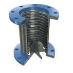
Vane Flex
Energy-Saving Pump Connectors
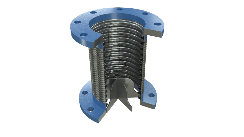
Flexible pump connector conditions flow at pump discharge New Vane Flex™ dramatically reduces pump turbulence and improves flow of engineered piping system. Piping engineers now have a more compact, efficient solution to reduce turbulence and straighten flow. The new Vane…
Product Description
Product Highlights
Additional Resources
Submittals
Product Description
Flexible pump connector conditions flow at pump discharge
New Vane Flex™ dramatically reduces pump turbulence and improves flow of engineered piping system.
Piping engineers now have a more compact, efficient solution to reduce turbulence and straighten flow. The new Vane Flex™ pump connector not only exceeds flow-straightening values recommended by all major manufacturers of balancing-type valves, it does it in a fraction of space.
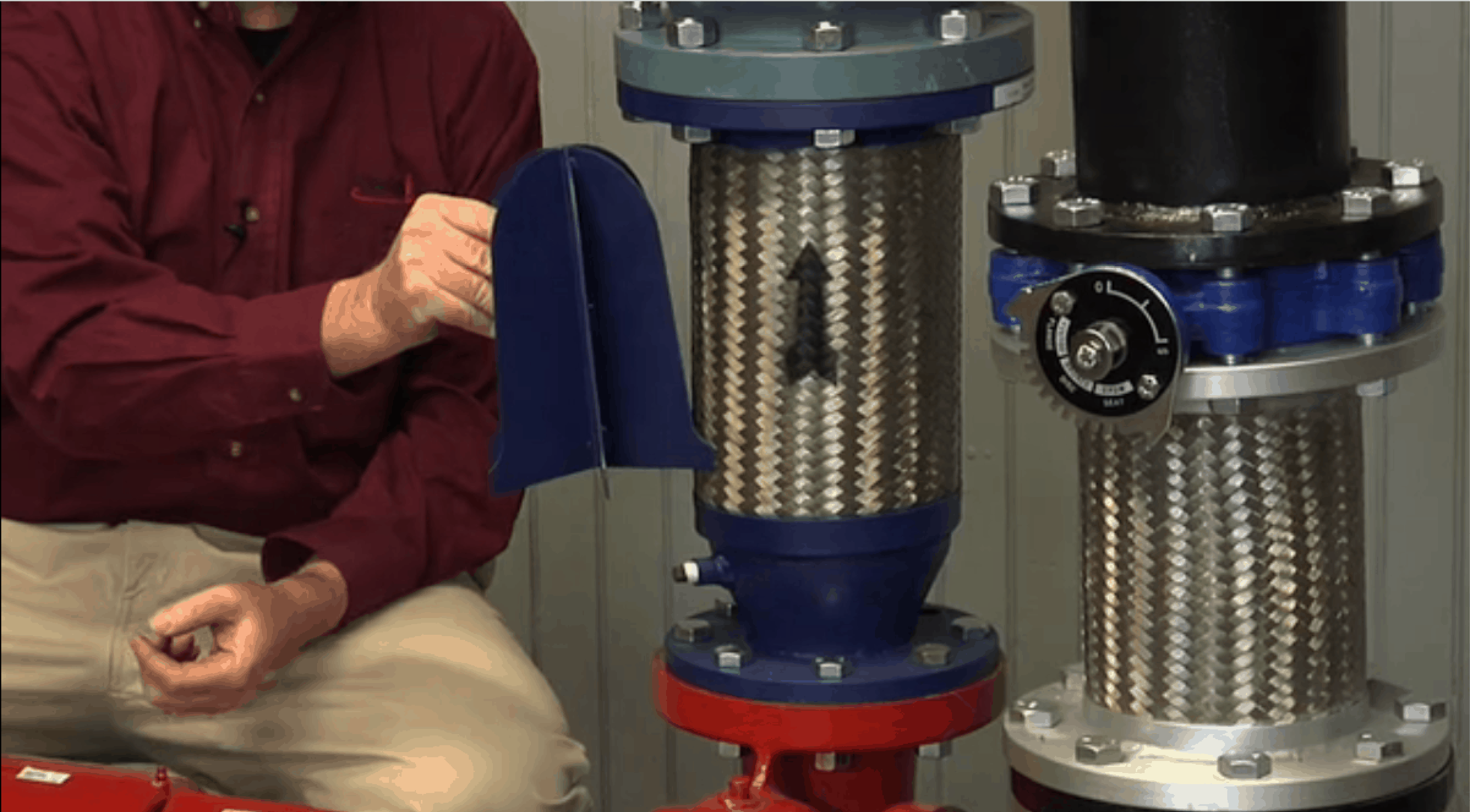
How does the Vane Flex Work?
Combining hydrodynamic-shaped vanes with a flexible pump connector, the Vane Flex maintains the full range of movement of a standard flexible connector, yet, at the same time and in the same space as a standard connector, provides better flow-straightening than a length of pipe equivalent to 5-to-10 diameters.
In addition, the Vane Flex provides the same stress relief and vibration in the same face-to-face as a standard pump connector.
Why is turbulence so damaging?
Valve flutter & poor balancing
Turbulence causes disc flutter, which causes wear, which is why older valves won’t close completely. Useful life is reduced, and most importantly, results in poor balancing. A spool piece of 5 to 10 diameters of pipe after the pump/before the valve was the universal fix suggested to minimize turbulence.
How can a Vane Flex be less expensive than a length of pipe?
First, 5 to 10 diameters length of pipe is valuable space. Secondly, the cost of the pipe and the cost of flanges and labor to weld and install this recommended length is already more expensive than the Vane Flex.
But most important… What’s specified versus what is actually installed in the field doesn’t always match, resulting in difficulty in balancing the system and premature valve wear.
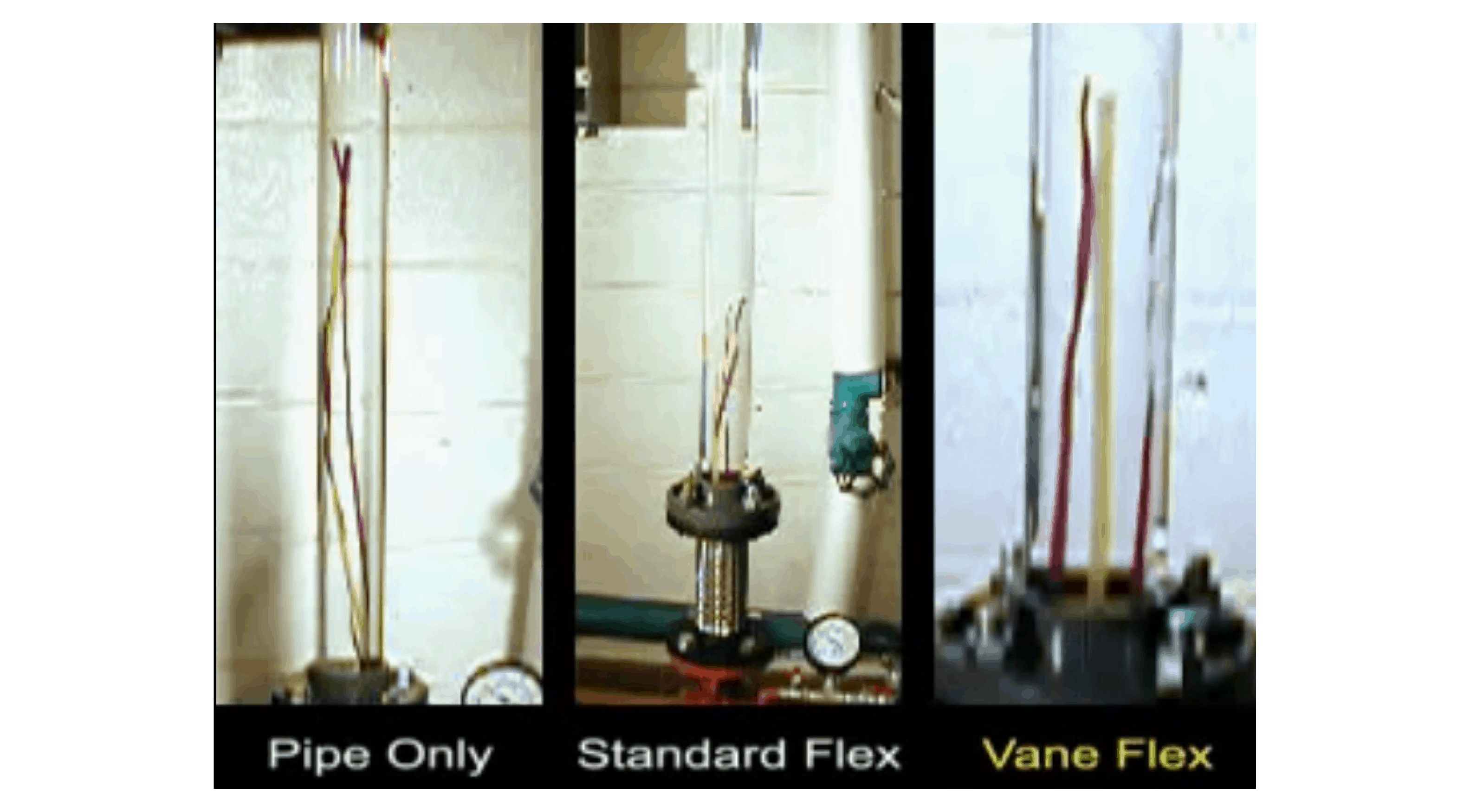
Vane flex vs. 10 pipe diameters Independent testing at the Milwaukee School of Engineering
Visual Flow Tests conducted in the Hydraulics lab at the Milwaukee School of Engineering compared a length of pipe equivalent to 10 diameters, a standard flexible connector, and the Vane Flex. The results were dramatic.
10 pipe diameters: The testing showed there is still significant turbulence even at the recommended maximum 10 pipe diameters from the pumps.
Standard pump connector: Turbulence out of a pump connector that is connected directly to a pump is dramatically worse and would create difficulty in balancing the system.
Vane Flex pump connector: The testing showed Vane Flex exhibited a marked reduction in flow turbulence, far exceeding even the 10 pipe diameters requested by every system balancing valve maker. This equates to a positive impact on the performance of the engineered pipe system.
Product Highlights
- Reduces discharge turbulence in fraction of space
- Hydrodynamic shaped vanes
- Protects valves immediately downstream of pump
- Equals 5-10 pipe diameter turbulence reduction
- Less pressure drop than 5-10 pipe diameter
- Vibration isolating pump connector
Additional Resources
Submittals
150# Plate Flanges
150# Plate Flanges and Long Radius 90 Degree Elbow
150# Plate Flange X Groove End and L.R. 90 Degree Elbow
150# Plate Flanges and 90 Degree Reducing Elbow
150# Plate Flange X Groove End and 90 Degree Reducing Elbow
150# Plate Flange X Groove End
150# Plate Flanges and Concentric Reducer
150# Plate Flange and Concentric Reducer x Groove
VANE FLEX - 150# PLATE FLANGES
| Model No. | Size | OAL | Permanent Offset |
Intermittent Offset |
Pressure at 70°F |
3D Drawing |
|---|---|---|---|---|---|---|
| VF0200 | 2 | 9 | .375″ | .125″ | 455 | Revit/CAD |
| VF0250 | 2.5 | 9 | .375″ | .125″ | 345 | Revit/CAD |
| VF0300 | 3 | 9 | .375″ | .125″ | 289 | Revit/CAD |
| VF0400 | 4 | 9 | .375″ | .125″ | 300 | Revit/CAD |
| VF0500 | 5 | 11 | .375″ | .125″ | 220 | Revit/CAD |
| VF0600 | 6 | 11 | .375″ | .125″ | 200 | Revit/CAD |
| VF0800 | 8 | 12 | .375″ | .125″ | 190 | Revit/CAD |
| VF1000 | 10 | 13 | .375″ | .125″ | 150 | Revit/CAD |
| VF1200 | 12 | 14 | .375″ | .125″ | 125 | Revit/CAD |
| VF1400 | 14 | 14 | .375″ | .125″ | 105 | Revit/CAD |
VANE FLEX - 150# PLATE FLANGED X GROOVE END AND L.R. 90° ELBOW
| Model No. | Size | A* | B* | Permanent Offset |
Intermittent Offset |
Pressure at 70°F |
3D Drawing |
|---|---|---|---|---|---|---|---|
| VF90FG0200 | 2 | 14.25 | 3.25 | .375″ | .125″ | 455 | Revit/CAD |
| VF90FG0250 | 2.5 | 15 | 4 | .375″ | .125″ | 345 | Revit/CAD |
| VF90FG0300 | 3 | 15.75 | 4.75 | .375″ | .125″ | 289 | Revit/CAD |
| VF90FG0400 | 4 | 17.25 | 6.25 | .375″ | .125″ | 300 | Revit/CAD |
| VF90FG0500 | 5 | 20.75 | 7.75 | .375″ | .125″ | 220 | Revit/CAD |
| VF90FG0600 | 6 | 22.25 | 9.25 | .375″ | .125″ | 200 | Revit/CAD |
| VF90FG0800 | 8 | 26.75 | 12.25 | .375″ | .125″ | 190 | Revit/CAD |
| VF90FG1000 | 10 | 30.75 | 15.25 | .375″ | .125″ | 150 | Revit/CAD |
| VF90FG1200 | 12 | 34.75 | 18.25 | .375″ | .125″ | 125 | Revit/CAD |
| VF90FG1400 | 14 | 37.75 | 21.25 | .375″ | .125″ | 105 | Revit/CAD |
VANE FLEX - 150# PLATE FLANGED AND 90° REDUCING ELBOW
| Model No. | Size | A* | B* | Permanent Offset |
Intermittent Offset |
Pressure at 70°F |
3D Drawing |
|---|---|---|---|---|---|---|---|
| VF90R0225 | 2 x 2.5 | 12.25 | 4 | .375″ | .125″ | 345 | Revit/CAD |
| VF90R0203 | 2 x 3 | 13 | 4.75 | .375″ | .125″ | 289 | Revit/CAD |
| VF90R2503 | 2.5 x 3 | 13 | 4.75 | .375″ | .125″ | 289 | Revit/CAD |
| VF90R0204 | 2 x 4 | 14.5 | 6.25 | .375″ | .125″ | 300 | Revit/CAD |
| VF90R2504 | 2.5 x 4 | 14.5 | 6.25 | .375″ | .125″ | 300 | Revit/CAD |
| VF90R0304 | 3 x 4 | 14.5 | 6.25 | .375″ | .125″ | 300 | Revit/CAD |
| VF90R2505 | 2.5 x 5 | 18 | 7.75 | .375″ | .125″ | 220 | Revit/CAD |
| VF90R0305 | 3 x 5 | 18 | 7.75 | .375″ | .125″ | 220 | Revit/CAD |
| VF90R0405 | 4 x 5 | 18 | 7.75 | .375″ | .125″ | 220 | Revit/CAD |
| VF90R0306 | 3 x 6 | 19.5 | 9.25 | .375″ | .125″ | 200 | Revit/CAD |
| VF90R0406 | 4 x 6 | 19.5 | 9.25 | .375″ | .125″ | 200 | Revit/CAD |
| VF90R0506 | 5 x 6 | 19.5 | 9.25 | .375″ | .125″ | 200 | Revit/CAD |
| VF90R0408 | 4 x 8 | 23.25 | 12.25 | .375″ | .125″ | 190 | Revit/CAD |
| VF90R0508 | 5 x 8 | 23.25 | 12.25 | .375″ | .125″ | 190 | Revit/CAD |
| VF90R0608 | 6 x 8 | 23.25 | 12.25 | .375″ | .125″ | 190 | Revit/CAD |
| VF90R0610 | 6 x 10 | 27.25 | 15.25 | .375″ | .125″ | 150 | Revit/CAD |
| VF90R0810 | 8 x 10 | 27.25 | 15.25 | .375″ | .125″ | 150 | Revit/CAD |
| VF90R1012 | 10 x 12 | 31.25 | 18.25 | .375″ | .125″ | 125 | Revit/CAD |
VANE FLEX - 150# PLATE FLANG X GROOVE ENDS AND 90° REDUCING ELBOW
| Model No. | Size | A* | B* | Permanent Offset |
Intermittent Offset |
Pressure at 70°F |
3D Drawing |
|---|---|---|---|---|---|---|---|
| VF90RFG0225 | 2 x 2.5 | 12.25 | 4 | .375″ | .125″ | 345 | Revit/CAD |
| VF90RFG0203 | 2 x 3 | 15.75 | 4.75 | .375″ | .125″ | 289 | Revit/CAD |
| VF90RFG2503 | 2.5 x 3 | 15.75 | 4.75 | .375″ | .125″ | 289 | Revit/CAD |
| VF90RFG0204 | 2 x 4 | 17.25 | 6.25 | .375″ | .125″ | 300 | Revit/CAD |
| VF90RFG2504 | 2.5 x 4 | 17.25 | 6.25 | .375″ | .125″ | 300 | Revit/CAD |
| VF90RFG0304 | 3 x 4 | 17.25 | 6.25 | .375″ | .125″ | 300 | Revit/CAD |
| VF90RFG2505 | 2.5 x 5 | 20.75 | 7.75 | .375″ | .125″ | 220 | Revit/CAD |
| VF90RFG0305 | 3 x 5 | 20.75 | 7.75 | .375″ | .125″ | 220 | Revit/CAD |
| VF90RFG0405 | 4 x 5 | 20.75 | 7.75 | .375″ | .125″ | 220 | Revit/CAD |
| VF90RFG0306 | 3 x 6 | 22.25 | 9.25 | .375″ | .125″ | 200 | Revit/CAD |
| VF90RFG0406 | 4 x 6 | 22.25 | 9.25 | .375″ | .125″ | 200 | Revit/CAD |
| VF90RFG0506 | 5 x 6 | 22.25 | 9.25 | .375″ | .125″ | 200 | Revit/CAD |
| VF90RFG0408 | 4 x 8 | 26.75 | 12.25 | .375″ | .125″ | 190 | Revit/CAD |
| VF90RFG0508 | 5 x 8 | 26.75 | 12.25 | .375″ | .125″ | 190 | Revit/CAD |
| VF90RFG0608 | 6 x 8 | 26.75 | 12.25 | .375″ | .125″ | 190 | Revit/CAD |
| VF90RFG0610 | 6 x 10 | 30.75 | 15.25 | .375″ | .125″ | 150 | Revit/CAD |
| VF90RFG0810 | 8 x 10 | 30.75 | 15.25 | .375″ | .125″ | 150 | Revit/CAD |
| VF90RFG1012 | 10 x 12 | 34.75 | 18.25 | .375″ | .125″ | 125 | Revit/CAD |
VANE FLEX - 150# PLATE FLANGES AND L.R. 90° ELBOW
| Model No. | Size | A* | B* | Permanent Offset |
Intermittent Offset |
Pressure at 70°F |
3D Drawing |
|---|---|---|---|---|---|---|---|
| VF900200 | 2 | 11.5 | 3.25 | .375″ | .125″ | 455 | Revit/CAD |
| VF900250 | 2.5 | 12.25 | 4 | .375″ | .125″ | 345 | Revit/CAD |
| VF900300 | 3 | 13 | 4.75 | .375″ | .125″ | 289 | Revit/CAD |
| VF900400 | 4 | 14.5 | 6.25 | .375″ | .125″ | 300 | Revit/CAD |
| VF900500 | 5 | 18 | 7.75 | .375″ | .125″ | 220 | Revit/CAD |
| VF900600 | 6 | 19.5 | 9.25 | .375″ | .125″ | 200 | Revit/CAD |
| VF900800 | 8 | 23.25 | 12.25 | .375″ | .125″ | 190 | Revit/CAD |
| VF901000 | 10 | 27.25 | 15.25 | .375″ | .125″ | 150 | Revit/CAD |
| VF901200 | 12 | 31.25 | 18.25 | .375″ | .125″ | 125 | Revit/CAD |
| VF901400 | 14 | 34.25 | 21.25 | .375″ | .125″ | 105 | Revit/CAD |
VANE FLEX - 150# PLATE FLANGES X GROOVED END
| Model No. | Size | OAL | Permanent Offset |
Intermittent Offset |
Pressure at 70°F |
3D Drawing |
|---|---|---|---|---|---|---|
| VFFG0200 | 2 | 11.75 | .375″ | .125″ | 455 | Revit/CAD |
| VFFG0250 | 2.5 | 11.75 | .375″ | .125″ | 345 | Revit/CAD |
| VFFG0300 | 3 | 11.75 | .375″ | .125″ | 289 | Revit/CAD |
| VFFG0400 | 4 | 11.75 | .375″ | .125″ | 300 | Revit/CAD |
| VFFG0500 | 5 | 13.50 | .375″ | .125″ | 220 | Revit/CAD |
| VFFG0600 | 6 | 13.50 | .375″ | .125″ | 200 | Revit/CAD |
| VFFG0800 | 8 | 15.25 | .375″ | .125″ | 190 | Revit/CAD |
| VFFG1000 | 10 | 16.25 | .375″ | .125″ | 150 | Revit/CAD |
| VFFG1200 | 12 | 17.25 | .375″ | .125″ | 125 | Revit/CAD |
| VFFG1400 | 14 | 17.25 | .375″ | .125″ | 105 | Revit/CAD |
VANE FLEX - 150# PLATE FLANGES AND CONCENTRIC REDUCER
| Model No. | Size | OAL | Permanent Offset |
Intermittent Offset |
Pressure at 70°F |
3D Drawing |
|---|---|---|---|---|---|---|
| VFR0225 | 2 x 2.5 | 12.25 | .375″ | .125″ | 345 | Revit/CAD |
| VFR0203 | 2 x 3 | 12.25 | .375″ | .125″ | 289 | Revit/CAD |
| VFR2503 | 2.5 x 3 | 12.25 | .375″ | .125″ | 289 | Revit/CAD |
| VFR0204 | 2 x 4 | 12.75 | .375″ | .125″ | 300 | Revit/CAD |
| VFR2504 | 2.5 x 4 | 12.75 | .375″ | .125″ | 300 | Revit/CAD |
| VFR0304 | 3 x 4 | 12.75 | .375″ | .125″ | 300 | Revit/CAD |
| VFR2505 | 2.5 x 5 | 15.75 | .375″ | .125″ | 220 | Revit/CAD |
| VFR0305 | 3 x 5 | 15.75 | .375″ | .125″ | 220 | Revit/CAD |
| VFR0405 | 4 x 5 | 15.75 | .375″ | .125″ | 220 | Revit/CAD |
| VFR0306 | 3 x 6 | 16.25 | .375″ | .125″ | 200 | Revit/CAD |
| VFR0406 | 4 x 6 | 16.25 | .375″ | .125″ | 200 | Revit/CAD |
| VFR0506 | 5 x 6 | 16.25 | .375″ | .125″ | 200 | Revit/CAD |
| VFR0408 | 4 x 8 | 17.50 | .375″ | .125″ | 190 | Revit/CAD |
| VFR0508 | 5 x 8 | 17.50 | .375″ | .125″ | 190 | Revit/CAD |
| VFR0608 | 6 x 8 | 17.50 | .375″ | .125″ | 190 | Revit/CAD |
| VFR0610 | 6 x 10 | 19.50 | .375″ | .125″ | 150 | Revit/CAD |
| VFR0810 | 8 x 10 | 19.50 | .375″ | .125″ | 150 | Revit/CAD |
| VFR1012 | 10 x 12 | 21.50 | .375″ | .125″ | 125 | Revit/CAD |
Vane Flex - 150# Plate Flange and Concentric Reducer x Groove
| Model No. | Pipe Size | A | Permanent Offset |
Intermittent Offset |
Pressure Rating (PSI)* |
Weight (Lbs.) |
3D Drawing | |
|---|---|---|---|---|---|---|---|---|
| Smaller | Larger | |||||||
| VFRFG0225 | 2” | 2-1/2” | 15” | .375” | .125” | 387 | 17 | Revit/CAD |
| VFRFG0203 | 2“ | 3” | 15” | .375” | .125” | 316 | 18 | Revit/CAD |
| VFRFG2503 | 2-1/2” | 3” | 15” | .375” | .125” | 316 | 19 | Revit/CAD |
| VFRFG0204 | 2” | 4” | 15-1/2” | .375” | .125” | 232 | 24 | Revit/CAD |
| VFRFG2504 | 2-1/2” | 4” | 15-1/2” | .375” | .125” | 232 | 24 | Revit/CAD |
| VFRFG0304 | 3” | 4” | 15-1/2” | .375” | .125” | 232 | 25 | Revit/CAD |
| VFRFG2505 | 2-1/2” | 5” | 18-1/2” | .375” | .125” | 191 | 33 | Revit/CAD |
| VFRFG0305 | 3” | 5” | 18-1/2” | .375” | .125” | 191 | 33 | Revit/CAD |
| VFRFG0405 | 4” | 5” | 18-1/2” | .375” | .125” | 191 | 34 | Revit/CAD |
| VFRFG0306 | 3” | 6” | 19” | .375” | .125” | 165 | 39 | Revit/CAD |
| VFRFG0406 | 4” | 6” | 19” | .375” | .125” | 165 | 39 | Revit/CAD |
| VFRFG0506 | 5” | 6” | 19” | .375” | .125” | 165 | 40 | Revit/CAD |
| VFRFG0408 | 4” | 8” | 21” | .375” | .125” | 234 | 67 | Revit/CAD |
| VFRFG0508 | 5” | 8” | 21” | .375” | .125” | 234 | 68 | Revit/CAD |
| VFRFG0608 | 6” | 8” | 21” | .375” | .125” | 234 | 68 | Revit/CAD |
| VFRFG0610 | 6” | 10” | 23” | .375” | .125” | 230 | 100 | Revit/CAD |
| VFRFG0810 | 8” | 10” | 23” | .375” | .125” | 230 | 102 | Revit/CAD |
| VFRFG1012 | 10” | 12” | 25” | .375” | .125” | 161 | 142 | Revit/CAD |