V-Loop Expansion Joint
Metraloop®
The Metraflex V-Loop can be used for both seismic and thermal applications. Like all the products in the Metraloop family of products, the V-Loop does not develop thrust loads and this results in almost eliminating the need for guides, simplifying…
Product Description
Product Highlights
Additional Resources
Submittals
Product Description
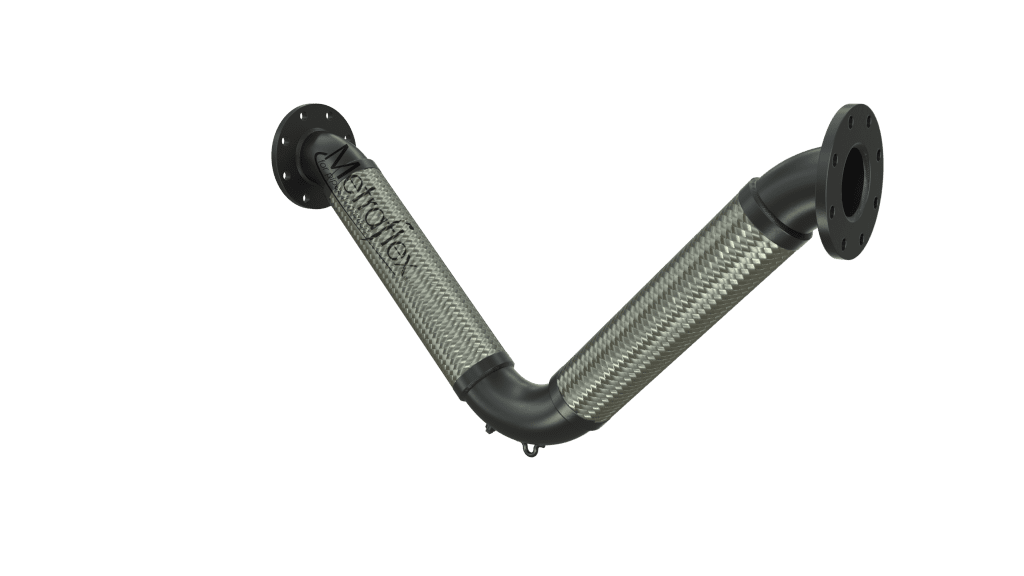
The Metraflex V-Loop can be used for both seismic and thermal applications. Like all the products in the Metraloop family of products, the V-Loop does not develop thrust loads and this results in almost eliminating the need for guides, simplifying anchor design when compared to in line bellows expansion joints.
The Metraloop V-loop has many of the advantages of the standard Metraloop expansion joint. Although it has a longer footprint, it also has a shorter offset than a Metraloop, allowing installation in tighter spaces.
One operational difference between the Metraloop and the V-Loop is that the return fitting on a V-Loop will move much more than on a Metraloop.
View Pressure Drop Data
Options
- Liners for high velocity or abrasive material
- Exterior coatings for protection in corrosive environments.
- Double braided for high pressure or steam applications.
- Any fitting that can be welded or brazed to can be used.
Refer to table for temperature and pressure ratings.
Product Highlights
- Absorbs both thermal growth and seismic movement in piping systems
- Does not develop thrust loads like in line bellows, resulting in very low anchor loads and guiding requirements.
- It takes up less space and takes less time to install than a hard pipe loop.
- Capable of movement in all directions
- Available in stock and custom configuration up to 36” diameter
- Proudly made in the USA
Additional Resources
Submittals
Grooved Ends, 2-inches of movement
Grooved Ends, 3-inches of movement
Grooved Ends, 4-inches of movement
Flanged Ends, 2-inches of movement
Flanged Ends, 3-inches of movement
Flanged Ends, 4-inches of movement
Sweat Ends, 2-inches of movement
Sweat Ends, 3-inches of movement
Sweat Ends, 4-inches of movement
Threaded Ends, 2-inches of movement
Threaded Ends, 3-inches of movement
Threaded Ends, 4-inches of movement
Weld Ends, 2-inches of movement
Weld Ends, 3-inches of movement
Weld Ends, 4-inches of movement
VRF V-Loop
Thread Ends for Gas Service
Weld Ends for Gas Service
Stainless Steel Weld Ends for Gas Service
Stainless Steel Thread Ends for Gas Service
150# RFSO Flanges For Gas Service
Stainless Steel 150# RFSO Flanges For Gas Service
DWV V-Loop No Hub Connection, 4"
DWV V-Loop No Hub Connection, 8"
DWV V-Loop Floating Flanges, 4"
DWV V-Loop Floating Flanges, 8"
UPC Listed V-Loop Sweat Ends, 4"
V-LOOP FLANGED ENDS
| Pipe Size | Model # | Movement | End to End | Length | PSI | Anchor Load | 3D Drawing |
|---|---|---|---|---|---|---|---|
| 2″ | VLF40200 | ±2″ | 25-7/8″ | 11-1/4″ | 500 | 82 | Revit/CAD |
| VLF60200 | ±3″ | 29″ | 12-7/8″ | Revit/CAD | |||
| VLF80200 | ±4″ | 31-3/4″ | 14-1/4″ | Revit/CAD | |||
| 2-1/2″ | VLF40250 | ±2″ | 31-1/8″ | 13-3/8″ | 387 | 87 | Revit/CAD |
| VLF60250 | ±3″ | 34-3/4″ | 15-1/4″ | Revit/CAD | |||
| VLF80250 | ±4″ | 38″ | 16-7/8″ | Revit/CAD | |||
| 3″ | VLF40300 | ±2″ | 33-3/4″ | 14-1/2″ | 288 | 93 | Revit/CAD |
| VLF60300 | ±3″ | 37-5/8″ | 16-1/2″ | Revit/CAD | |||
| VLF80300 | ±4″ | 41″ | 18-1/8″ | Revit/CAD | |||
| 4″ | VLF40400 | ±2″ | 39-1/2″ | 16-3/4″ | 232 | 127 | Revit/CAD |
| VLF60400 | ±3″ | 43-3/4″ | 18-7/8″ | Revit/CAD | |||
| VLF80400 | ±4″ | 47-3/8″ | 20-3/4″ | Revit/CAD | |||
| 5″ | VLF40500 | ±2″ | 45″ | 18-7/8″ | 200 | 214 | Revit/CAD |
| VLF60500 | ±3″ | 49-5/8″ | 21-1/8″ | Revit/CAD | |||
| VLF80500 | ±4″ | 53-1/2″ | 23-1/8″ | Revit/CAD | |||
| 6″ | VLF40600 | ±2″ | 50-7/8″ | 21″ | 170 | 228 | Revit/CAD |
| VLF60600 | ±3″ | 55-7/8″ | 23-1/2″ | Revit/CAD | |||
| VLF80600 | ±4″ | 60″ | 25-5/8″ | Revit/CAD | |||
| 8″ | VLF40800 | ±2″ | 60-5/8″ | 24-3/8″ | 212 | 312 | Revit/CAD |
| VLF60800 | ±3″ | 65-3/4″ | 27″ | Revit/CAD | |||
| VLF80800 | ±4″ | 70-1/8″ | 29-1/8″ | Revit/CAD | |||
| 10″ | VLF41000 | ±2″ | 71-3/4″ | 28-1/2″ | 175 | 345 | Revit/CAD |
| VLF61000 | ±3″ | 77-5/8″ | 31-1/2″ | Revit/CAD | |||
| VLF81000 | ±4″ | 82-1/2″ | 33-7/8″ | Revit/CAD | |||
| 12″ | VLF41200 | ±2″ | 82-3/4″ | 32-1/2″ | 160 | 399 | Revit/CAD |
| VLF61200 | ±3″ | 89-1/8″ | 35-3/4″ | Revit/CAD | |||
| VLF81200 | ±4″ | 94-1/2″ | 38-3/8″ | Revit/CAD |
V-LOOP GROOVED ENDS
| Pipe Size | Model # | Movement | End to End | Length | PSI | Anchor Load | 3D Drawing |
|---|---|---|---|---|---|---|---|
| 2″ | VLG40200 | ±2″ | 31-3/8″ | 11-1/4″ | 500 | 82 | Revit/CAD |
| VLG60200 | ±3″ | 34-1/2″ | 12-7/8″ | Revit/CAD | |||
| VLG80200 | ±4″ | 37-1/4″ | 14-1/4″ | Revit/CAD | |||
| 2-1/2″ | VLG40250 | ±2″ | 36-5/8″ | 13-3/8″ | 387 | 87 | Revit/CAD |
| VLG60250 | ±3″ | 40-1/4″ | 15-1/4″ | Revit/CAD | |||
| VLG80250 | ±4″ | 43-1/2″ | 16-7/8″ | Revit/CAD | |||
| 3″ | VLG40300 | ±2″ | 39-1/4″ | 14-1/2″ | 288 | 93 | Revit/CAD |
| VLG60300 | ±3″ | 43-1/8″ | 16-1/2″ | Revit/CAD | |||
| VLG80300 | ±4″ | 46-1/2″ | 18-1/8″ | Revit/CAD | |||
| 4″ | VLG40400 | ±2″ | 45″ | 16-3/4″ | 232 | 127 | Revit/CAD |
| VLG60400 | ±3″ | 49-1/4″ | 18-7/8″ | Revit/CAD | |||
| VLG80400 | ±4″ | 52-7/8″ | 20-3/4″ | Revit/CAD | |||
| 5″ | VLG40500 | ±2″ | 50-1/2″ | 18-7/8″ | 200 | 214 | Revit/CAD |
| VLG60500 | ±3″ | 55-1/8″ | 21-1/8″ | Revit/CAD | |||
| VLG80500 | ±4″ | 59″ | 23-1/8″ | Revit/CAD | |||
| 6″ | VLG40600 | ±2″ | 56-3/8″ | 21″ | 170 | 228 | Revit/CAD |
| VLG60600 | ±3″ | 61-3/8″ | 23-1/2″ | Revit/CAD | |||
| VLG80600 | ±4″ | 65-1/2″ | 25-5/8″ | Revit/CAD | |||
| 8″ | VLG40800 | ±2″ | 68-1/8″ | 24-3/8″ | 212 | 312 | Revit/CAD |
| VLG60800 | ±3″ | 73-1/4″ | 27″ | Revit/CAD | |||
| VLG80800 | ±4″ | 77-5/8″ | 29-1/8″ | Revit/CAD | |||
| 10″ | VLG41000 | ±2″ | 79-1/4″ | 28-1/2″ | 175 | 345 | Revit/CAD |
| VLG61000 | ±3″ | 85-1/8″ | 31-1/2″ | Revit/CAD | |||
| VLG81000 | ±4″ | 90″ | 33-7/8″ | Revit/CAD | |||
| 12″ | VLG41200 | ±2″ | 90-1/4″ | 32-1/2″ | 160 | 399 | Revit/CAD |
| VLG61200 | ±3″ | 96-5/8″ | 35-3/4″ | Revit/CAD | |||
| VLG81200 | ±4″ | 102″ | 38-3/8″ | Revit/CAD |
V-LOOP SWEAT ENDS
| Pipe Size | Model # | Movement | End to End | Length | PSI | Anchor Load | 3D Drawing |
|---|---|---|---|---|---|---|---|
| 1/2″ | VLS40050 | ±2″ | 15-1/8″ | 7″ | 566 | 35 | Revit/CAD |
| VLS60050 | ±3″ | 17-3/8″ | 8-1/8″ | Revit/CAD | |||
| VLS80050 | ±4″ | 19-1/4″ | 9″ | Revit/CAD | |||
| 3/4″ | VLS40075 | ±2″ | 17-7/8″ | 8-1/8″ | 468 | 41 | Revit/CAD |
| VLS60075 | ±3″ | 20-1/4″ | 9-1/4″ | Revit/CAD | |||
| VLS80075 | ±4″ | 22-1/4″ | 10-1/4″ | Revit/CAD | |||
| 1″ | VLS40100 | ±2″ | 20-7/8″ | 9-3/8″ | 334 | 46 | Revit/CAD |
| VLS60100 | ±3″ | 23-1/2″ | 10-5/8″ | Revit/CAD | |||
| VLS80100 | ±4″ | 25-3/4″ | 11-3/4″ | Revit/CAD | |||
| 1-1/4″ | VLS40125 | ±2″ | 23-3/8″ | 10-1/2″ | 306 | 65 | Revit/CAD |
| VLS60125 | ±3″ | 26-1/4″ | 12″ | Revit/CAD | |||
| VLS80125 | ±4″ | 28-3/4″ | 13-1/4″ | Revit/CAD | |||
| 1-1/2″ | VLS40150 | ±2″ | 25-1/8″ | 11-1/4″ | 297 | 68 | Revit/CAD |
| VLS60150 | ±3″ | 28-1/8″ | 12-3/4″ | Revit/CAD | |||
| VLS80150 | ±4″ | 30-3/4″ | 14-1/8″ | Revit/CAD | |||
| 2″ | VLS40200 | ±2″ | 27-3/4″ | 12-3/8″ | 210 | 82 | Revit/CAD |
| VLS60200 | ±3″ | 31-1/4″ | 14/1/8″ | Revit/CAD | |||
| VLS80200 | ±4″ | 34-1/8″ | 15-5/8″ | Revit/CAD | |||
| 2-1/2″ | VLS40250 | ±2″ | 32″ | 14-1/4″ | 194 | 87 | Revit/CAD |
| VLS60250 | ±3″ | 35-7/8″ | 16-1/8″ | Revit/CAD | |||
| VLS80250 | ±4″ | 39-1/8″ | 17-3/4″ | Revit/CAD | |||
| 3″ | VLS40300 | ±2″ | 34-1/8″ | 15-1/4″ | 166 | 93 | Revit/CAD |
| VLS60300 | ±3″ | 38-1/8″ | 17-1/4″ | Revit/CAD | |||
| VLS80300 | ±4″ | 41-5/8″ | 19″ | Revit/CAD | |||
| 4″ | VLS40400 | ±2″ | 39-1/8″ | 17-3/8″ | 109 | 127 | Revit/CAD |
| VLS60400 | ±3″ | 43-3/8″ | 19-1/4″ | Revit/CAD | |||
| VLS80400 | ±4″ | 47″ | 21″ | Revit/CAD |
V-LOOP THREAD ENDS
| Pipe Size | Model # | Movement | End to End | Length | PSI | Anchor Load | 3D Drawing |
|---|---|---|---|---|---|---|---|
| 1/2″ | VLT40050 | ±2″ | 21-1/8″ | 6-3/4″ | 1100 | 35 | Revit/CAD |
| VLT60050 | ±3″ | 23-1/4″ | 7-3/4″ | Revit/CAD | |||
| VLT80050 | ±4″ | 25″ | 8-3/4″ | Revit/CAD | |||
| 3/4″ | VLT40075 | ±2″ | 23-1/4″ | 7-3/4″ | 792 | 41 | Revit/CAD |
| VLT60075 | ±3″ | 25-3/4″ | 9″ | Revit/CAD | |||
| VLT80075 | ±4″ | 27-3/4″ | 10″ | Revit/CAD | |||
| 1″ | VLT40100 | ±2″ | 24-3/8″ | 8-3/8″ | 571 | 46 | Revit/CAD |
| VLT60100 | ±3″ | 26-7/8″ | 9-5/8″ | Revit/CAD | |||
| VLT80100 | ±4″ | 29″ | 10-3/4″ | Revit/CAD | |||
| 1-1/4″ | VLT40125 | ±2″ | 26-1/8″ | 9-1/8″ | 531 | 65 | Revit/CAD |
| VLT60125 | ±3″ | 28-7/8″ | 10-1/2″ | Revit/CAD | |||
| VLT80125 | ±4″ | 31-1/4″ | 11-5/8″ | Revit/CAD | |||
| 1-1/2″ | VLT40150 | ±2″ | 28″ | 9-7/8″ | 472 | 68 | Revit/CAD |
| VLT60150 | ±3″ | 30-7/8″ | 11-3/8″ | Revit/CAD | |||
| VLT80150 | ±4″ | 33-3/8″ | 12-1/2″ | Revit/CAD | |||
| 2″ | VLT40200 | ±2″ | 31-3/8″ | 11-1/4″ | 500 | 82 | Revit/CAD |
| VLT60200 | ±3″ | 34-1/2″ | 12-7/8″ | Revit/CAD | |||
| VLT80200 | ±4″ | 37-1/4″ | 14-1/4″ | Revit/CAD | |||
| 2-1/2″ | VLT40250 | ±2″ | 36-5/8″ | 13-3/8 | 387 | 87 | Revit/CAD |
| VLT60250 | ±3″ | 40-1/4″ | 15-1/4″ | Revit/CAD | |||
| VLT80250 | ±4″ | 43-1/2″ | 16-7/8″ | Revit/CAD | |||
| 3″ | VLT40300 | ±2″ | 39-1/4″ | 14-1/2″ | 288 | 93 | Revit/CAD |
| VLT60300 | ±3″ | 43-1/8″ | 16-1/2″ | Revit/CAD | |||
| VLT80300 | ±4″ | 46-1/2″ | 18-1/8″ | Revit/CAD | |||
| 4″ | VLT40400 | ±2″ | 47″ | 16-3/4″ | 232 | 127 | Revit/CAD |
| VLT60400 | ±3″ | 51-1/4″ | 18-7/8″ | Revit/CAD | |||
| VLT80400 | ±4″ | 54-7/8″ | 20-3/4″ | Revit/CAD |
V-LOOP WELD ENDS
| Pipe Size | Model # | Movement | End to End | Length | PSI | Anchor Load | 3D Drawing |
|---|---|---|---|---|---|---|---|
| 1/2″ | VLW40050 | ±2″ | 15-1/8″ | 6-3/4″ | 1100 | 35 | Revit/CAD |
| VLW60050 | ±3″ | 17-1/4″ | 7-3/4″ | Revit/CAD | |||
| VLW80050 | ±4″ | 19″ | 8-3/4″ | Revit/CAD | |||
| 3/4″ | VLW40075 | ±2″ | 17-1/4″ | 7-3/4″ | 792 | 41 | Revit/CAD |
| VLW60075 | ±3″ | 19-3/4″ | 9″ | Revit/CAD | |||
| VLW80075 | ±4″ | 21-3/4″ | 10″ | Revit/CAD | |||
| 1″ | VLW40100 | ±2″ | 18-3/8″ | 8-3/8″ | 571 | 46 | Revit/CAD |
| VLW60100 | ±3″ | 20-7/8″ | 9-5/8″ | Revit/CAD | |||
| VLW80100 | ±4″ | 23″ | 10-3/4″ | Revit/CAD | |||
| 1-1/4″ | VLW40125 | ±2″ | 20-1/8″ | 9-1/8″ | 531 | 65 | Revit/CAD |
| VLW60125 | ±3″ | 22-7/8″ | 10-1/2″ | Revit/CAD | |||
| VLW80125 | ±4″ | 25-1/4″ | 11-5/8″ | Revit/CAD | |||
| 1-1/2″ | VLW40150 | ±2″ | 22″ | 9-7/8″ | 472 | 68 | Revit/CAD |
| VLW60150 | ±3″ | 24-7/8″ | 11-3/8″ | Revit/CAD | |||
| VLW80150 | ±4″ | 27-3/8″ | 12-1/2″ | Revit/CAD | |||
| 2″ | VLW40200 | ±2″ | 25-3/8″ | 11-1/4″ | 500 | 82 | Revit/CAD |
| VLW60200 | ±3″ | 28-1/2″ | 12-7/8″ | Revit/CAD | |||
| VLW80200 | ±4″ | 31-1/4″ | 14-1/4″ | Revit/CAD | |||
| 2-1/2″ | VLW40250 | ±2″ | 30-5/8″ | 13-3/8″ | 387 | 87 | Revit/CAD |
| VLW60250 | ±3″ | 34-1/4″ | 15-1/4″ | Revit/CAD | |||
| VLW80250 | ±4″ | 37-1/2″ | 16-7/8″ | Revit/CAD | |||
| 3″ | VLW40300 | ±2″ | 33-1/4″ | 14-1/2″ | 288 | 93 | Revit/CAD |
| VLW60300 | ±3″ | 37-1/8″ | 16-1/2″ | Revit/CAD | |||
| VLW80300 | ±4″ | 40-1/2″ | 18-1/8″ | Revit/CAD | |||
| 4″ | VLW40400 | ±2″ | 39″ | 16-3/4″ | 232 | 127 | Revit/CAD |
| VLW60400 | ±3″ | 43-1/4″ | 18-7/8″ | Revit/CAD | |||
| VLW80400 | ±4″ | 46-7/8″ | 20-3/4″ | Revit/CAD | |||
| 5″ | VLW40500 | ±2″ | 44-1/2″ | 18-7/8″ | 200 | 214 | Revit/CAD |
| VLW60500 | ±3″ | 49-1/8″ | 21-1/8″ | Revit/CAD | |||
| VLW80500 | ±4″ | 53″ | 23-1/8″ | Revit/CAD | |||
| 6″ | VLW40600 | ±2″ | 50-3/8″ | 21″ | 170 | 228 | Revit/CAD |
| VLW60600 | ±3″ | 55-3/8″ | 23-1/2″ | Revit/CAD | |||
| VLW80600 | ±4″ | 59-1/2″ | 25-5/8″ | Revit/CAD | |||
| 8″ | VLW40800 | ±2″ | 60-1/8″ | 24-3/8″ | 212 | 312 | Revit/CAD |
| VLW60800 | ±3″ | 65-1/4″ | 27″ | Revit/CAD | |||
| VLW80800 | ±4″ | 69-5/8″ | 29-1/8″ | Revit/CAD | |||
| 10″ | VLW41000 | ±2″ | 71-1/4″ | 28-1/2″ | 175 | 345 | Revit/CAD |
| VLW61000 | ±3″ | 77-1/8″ | 31-1/2″ | Revit/CAD | |||
| VLW81000 | ±4″ | 82″ | 33-7/8″ | Revit/CAD | |||
| 12″ | VLW41200 | ±2″ | 82-1/4″ | 32-1/2″ | 160 | 399 | Revit/CAD |
| VLW61200 | ±3″ | 88-5/8″ | 35-3/4″ | Revit/CAD | |||
| VLW81200 | ±4″ | 94″ | 38-3/8″ | Revit/CAD |
VRF V-LOOP
| PART # | NOM SIZE | TUBE OD | WIDTH | HEIGHT | MOVEMENT | PRESSURE RATING | WEIGHT |
|---|---|---|---|---|---|---|---|
| VLVRF80050 | 1/2″ | 5/8″ | 42-1/8″ | 11-1/4″ | ±4″ | 700 PSI @ 300°F | 3 LBS |
| VLVRF80063 | 5/8″ | 3/4″ | 45-3/4″ | 13″ | ±4″ | 700 PSI @ 300°F | 5 LBS |
| VLVRF80075 | 3/4″ | 7/8″ | 45-3/4″ | 13″ | ±4″ | 700 PSI @ 300°F | 5 LBS |
| VLVRF80100 | 1″ | 1⅛” | 47-3/8″ | 13-7/8″ | ±4″ | 700 PSI @ 300°F | 7 LBS |
| VLVRF80125 | 1¼″ | 1⅜” | 50″ | 15-1/8″ | ±4″ | 700 PSI @ 300°F | 10 LBS |
| VLVRF80150 | 1½″ | 1 5/8″ | 52-5/8″ | 16-1/4″ | ±4″ | 700 PSI @ 300°F | 13 LBS |
| VLVRF80200 | 2″ | 2⅛” | 57-1/2″ | 18-3/8″ | ±4″ | 700 PSI @ 300°F | 19 LBS |
ALL VLOOPS FOR VRF SERVICE ARE RATED FOR FULL VACUUM.
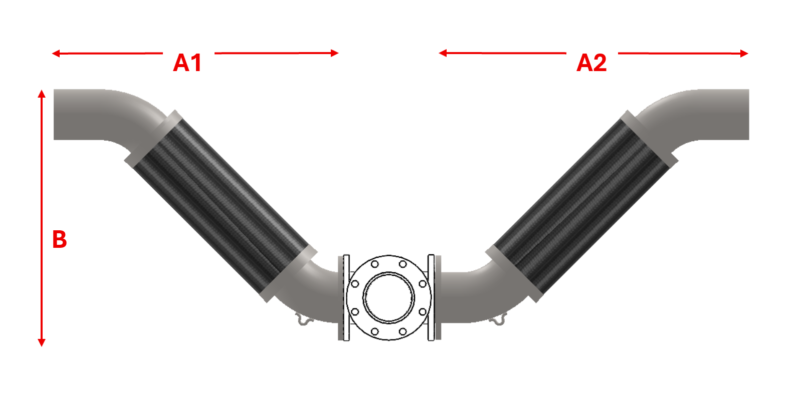
DWV V-LOOP - FLOATING FLANGES
| MODEL # | PIPE SIZE |
MOVEMENT | A1 (in.) |
A2 (in.) |
B (in.) |
PSI* |
|---|---|---|---|---|---|---|
| VLFILP80400 | 4″ | ± 4 | 28-3/8 | 31-1/8 | 22-3/8 | 150 PSI @ 70°F |
| VLFILP160400 | ± 8 | 34-1/2 | 37-1/4 | 28-1/2 | ||
| VLFILP80600 | 6″ | ± 4 | 35-1/8 | 38-3/8 | 27-1/8 | |
| VLFILP160600 | ± 8 | 42 | 45-1/4 | 34 | ||
| VLFILP80800 | 6″ | ± 4 | 41-3/4 | 45-1/2 | 31-7/8 | |
| VLFILP160800 | ± 8 | 49-3/8 | 53-1/8 | 39-1/2 | ||
| VLFILP81000 | 10″ | ± 4 | 48-3/4 | 53-1/2 | 36-3/8 | |
| VLFILP161000 | ± 8 | 57-1/8 | 61-7/8 | 44-3/4 | ||
| VLFILP81200 | 12″ | ± 4 | 56 | 61-3/4 | 41-1/8 | |
| VLFILP161200 | ± 8 | 65-1/8 | 70-7/8 | 50-1/4 |
DWV V-LOOP - NO HUB CONNECTION
| MODEL # | PIPE SIZE |
MOVEMENT | A1 (in.) |
A2 (in.) |
B (in.) |
PSI* |
|---|---|---|---|---|---|---|
| VLWILP80400 | 4″ | ± 4 | 31-3/8 | 34-1/8 | 22-3/8 | 150 PSI @ 70°F |
| VLWILP160400 | ± 8 | 37-1/2 | 40-1/4 | 28-1/2 | ||
| VLWILP80600 | 6″ | ± 4 | 37-5/8 | 40-7/8 | 27-1/8 | |
| VLWILP160600 | ± 8 | 44-1/2 | 47-3/4 | 34 | ||
| VLWILP80800 | 8″ | ± 4 | 43-3/4 | 47-1/2 | 31-7/8 | |
| VLWILP160800 | ± 8 | 51-3/8 | 55-1/8 | 39-1/2 | ||
| VLWILP81000 | 10″ | ± 4 | 49-3/4 | 54-1/2 | 36-3/8 | |
| VLWILP161000 | ± 8 | 58-1/8 | 62-7/8 | 44-3/4 | ||
| VLWILP81200 | 12″ | ± 4 | 56 | 61-3/4 | 41-1/8 | |
| VLWILP161200 | ± 8 | 65-1/8 | 70-7/8 | 50-1/4 |